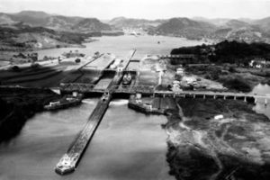
The original lock canal plan called for one three-step set of locks at Gatun, one step at Pedro Miguel and a two-step set at Sosa Hill. In late 1907, it was decided to move the Sosa Hill locks further inland to Miraflores, mostly because the new site provided a more stable construction foundation, but also because it afforded greater protection against sea bombardment.
The locks took their names from geographic names already in common use before the Canal was built. All lock chambers have the same 110 by 1,000 feet dimensions, and they are built in pairs. That is, two lanes of chambers run side by side to accommodate two lanes of traffic, either in opposite directions at the same time or in the same direction, depending on transit needs. Gatun Locks consists of three steps or pairs of chambers, there is one step at Pedro Miguel and two at Miraflores, making six pairs, 12 chambers in all. The locks have been called the structural triumph of the Panama Canal and are a unique aspect of the waterway. At the time of their construction, their overall mass, dimensions and innovative design surpassed any similar existing structures, and they are still considered to be an engineering wonder of the world.
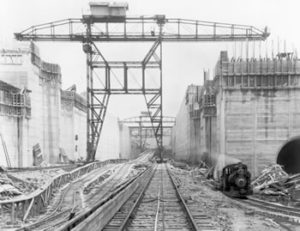
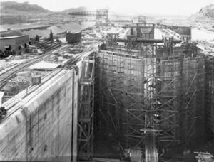
It took four years to build all of the locks from the first concrete being laid at Gatun on August 24, 1909. Until the late 1800s, concrete, a combination of sand, gravel and cement, had been little used in building, and then mostly for floors and basements. There was still a great deal to be learned and numerous decisions to be made in the science of concrete which requires specific, controlled measurements of water/cement/sand ratios and aggregate size, as well as careful timing of a streamlined delivery system from source to site. The concrete work in Panama was an unprecedented challenge that would not be equaled in total volume until construction of Boulder Dam in the 1930s.
In spite of the newness of the science, the results were extraordinary. After more than 80 years of service, the concrete of the Panama Canal locks and spillways is in near perfect condition, which to present-day engineers is among the most exceptional aspects of the entire Canal.
Canal organization ships, the Ancon and the Cristobal, brought all of the cement to build the locks, dams and spillways from New York. On the Atlantic side, gravel and sand came by water from areas east of Colon, the gravel from a large crushing plant in Portobelo and the sand from Nombre de Dios. For the Pacific side, rock was quarried and crushed at Ancon Hill; the sand came from Punta Chame in Panama Bay.
Three men, Lieutenant Colonel Harry Hodges, Edward Schildhauer and Henry Goldmark, were largely responsible for the engineering design of the locks. The work took years of advanced planning. Hodges was an Army officer and an invaluable assistant to Goethals, had overall responsibility for the design and construction of the lock gates, arguably the most difficult technical responsibility of the entire project. Goethals was to state that the Canal could not have been built without Hodges. Schildhauer was an electrical engineer and Goldmark was in charge of lock gate design.
The key factor in the whole Canal enterprise, of course, was, and is, water. Water lifts ships 85 feet above sea level to the surface of Gatun Lake, floats them across the Continental Divide and lowers them again to sea level in the opposite ocean. Water also serves to generate electrical power for the Canal to run the electric motors that open and close the gates and valves and the electric locks locomotives.
No pumps are used at the Panama Canal, the water does its work by force of gravity alone. Water is admitted or released through giant tunnels, or culverts, eighteen feet in diameter, running lengthwise within the center and side walls of the locks. Branching off at right angles to these culverts, smaller culverts run laterally under the floor of each lock chamber, 20 to each chamber. Each cross culvert has five openings for a total of 100 holes in each chamber for the water to enter or drain, depending on which valves are opened or closed. This large number of holes distributes the water evenly over the full floor area to control turbulence
To fill a lock, the main valves at the lower end of the chamber are closed, while those at the upper end are opened. The water pours from the lake through the large culverts into the cross culverts and up through the holes in the chamber floor. To release the water from the lock, the valves at the upper end are closed, while those at the lower end are opened.
The lock gates, or miter gates as they are known because they close in a wide V, are the Canal’s most dramatic moving parts. The gates swing like double doors. The hollow, watertight construction of their lower halves makes them buoyant in the water, greatly reducing the working load on their hinges. All gate leaves are 64 feet wide by 7 feet thick. However, they vary in height from 47 to 82 feet, depending on their position. For example, the Miraflores Locks lower chamber gates are the highest because of the extreme variation in the Pacific tides.
The design and manufacture of all of the lock gates was one of the Canal’s great engineering challenges and one of its greatest triumphs. The simple, yet powerful gate operating mechanism was designed by Edward Schildhauer. In its design he had no established model to go by. Yet every aspect of this critical mechanism had to be precision engineered and manufactured to work flawlessly and dependably. The gates had to swing easily, yet withstand enormous pressures. To operate, the lock gates leaves are connected by steel arms, called “struts,” to huge bull wheels constructed within the lock walls. Each 20-foot-diameter, horizontal-lying bull wheel is geared to an electric motor. When in operation, wheel and strut work like the driving wheel and connecting rod on a railroad locomotive to open and close the gates.
At Miraflores Locks, each lock chamber, except for the lower locks, has a set of intermediate gates. The purpose of these is to conserve water by reducing the size of the chamber, if the ship in transit is not one of the Panamax giants and be accommodated by a 600-foot chamber.
As the lock gates themselves are a form of dam and above sea level, precautions were taken to protect them from damage that could allow the lake water to escape and flow out to sea. One measure was to have double gates ahead of the vessel, an operating gate and a guard gate, at points where damage to a gate could join the two levels, that is, at the upper and lower ends of the upper lock in each flight and at both ends of the Pedro Miguel single-step lock.
Also, iron fender chains were installed to stretch across the chambers between the lock walls to protect the guard gates. Only after the ship was in proper position and under towing locomotive control was the chain lowered. The idea was that if a ship went out of control and struck the chain, an automatic release would let the chain out slowly until the ship came to a stop, thus limiting possible damage. The expense of their upkeep against the extreme unlikelihood of their use caused the Board of Directors to approve fender chain removal in July 1976, except at the upper ends of Gatun and Pedro Miguel locks; these remaining chains were removed in October 1980.
Yet another devise stood as safeguard should a ship break through a guard gate. That was what was called an emergency dam installed on the side walls at the entrance of each upper lock between the fender chain and the guard gates. It a big steel apparatus mounted to swing across the lock entrance in about two minutes in case of emergency. A series of wicket girders would descend forming runways down which huge steel plates would be dropped until the channel was sealed off. Never put to use, the emergency dams were removed in the mid 1950s.
Electricity was the power that ran Canal construction-era cableways, cranes, rock crushers and cement mixers. An all-electric canal was an innovation in the first decade of the 20th century. Locks operations required some 1,500 electric motors, as all controls were electrical. The General Electric Company produced about half the electrical equipment needed during construction and virtually all of the permanent motors, relays, switches, wiring and generating equipment. They also built the original locks towing locomotives and all of the lighting.
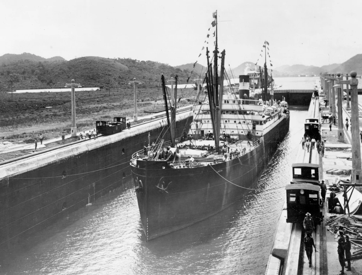
The electric towing locomotive system was designed to provide complete control over the movement of vessels transiting the locks. Designed by Schildhauer, the locomotives work on track built atop the lock walls operating at a speed of about 2 miles per hour. An important design factor was that they have to travel the 45-degree incline between the lock chambers. The locomotives were built in Schenectady, New York, at a unit cost of $13,000.
Schildhauer also designed the basic concept of the locks control system, though its development was a joint effort with General Electric. All locks operation is accomplished from a control house built on the center wall of the upper lock chamber. Here, from an unobstructed view of the entire locks flight and a cleverly designed control board, a single person can run every operation in the passage of a ship, except towing locomotive movement.
A control board is a waist-high working representation of the locks in miniature. Everything that happens in the locks happens on the control board at precisely the same time. The switches to work the lock gates and the other system mechanisms are located beside the representation of that devise on the control board. To lift a huge oceangoing ship in a lock chamber, the operator has only to turn a small chrome handle.
Another ingenious part of the system are elaborate racks of interlocking bars installed unseen below the control board to make the switches mechanically interlock. Each handle must be turned in proper sequence or it will not turn. This eliminates the possibility of doing anything out of order or forgetting a step.
Only in an electrically run system could the locks have been controlled from a central point. An individual motor in the system can be located as much as half a mile away from the control board. This same system has been in use virtually unchanged for more than eight decades, and it still works perfectly.
The Pacific-side locks were finished first, the single flight at Pedro Miguel second in 1911 and Miraflores in May of 1913. Exceptionally high morale permeated the entire work force at this time. On May 20, 1913, shovels No. 222 and No. 230, which had been slowly narrowing the gap in Culebra Cut, met “on the bottom of the Canal.” At 40 feet above sea level, the Cut had reached its full construction-era depth. Guard gates at Gatun performed flawlessly the second week of June 1913, and on June 27, the last of the Gatun Dam spillway gates was closed, allowing the lake to now rise to full height. Dry excavation ended three months later. When a January 1913 slide at Cucaracha spilled 2,000,000 cubic yards of earth into the Cut, it was decided to flood the Cut and finish the clearing by dredge. The last steam shovel lifted the last rock in the cut on the morning of September 10, 1913, to be hauled out on the last dirt train by locomotive No. 260.
The seagoing tug Gatun, an Atlantic entrance working tug used for hauling barges, had the honor on September 26, 1913, of making the first trial lockage of Gatun Locks. The lockage went perfectly, although all valves were controlled manually since the central control board was still not ready.
As if to further test the system, an earthquake struck on September 30, knocking seismograph needles off the scale at Ancon. Although there were landslides in the interior and cracked walls in some Panama City buildings, Gorgas reported to Washington that “There has been no damage whatever to any part of the Canal.”
Six big pipes in the earthen dike at Gamboa flooded Culebra Cut that same week. Then, on October 10, 1913, President Woodrow Wilson pressed a button in Washington and relayed by telegraph from Washington to New York to Galveston to Panama the signal that blew the center of the dike to complete the flooding of the Cut and join it to Gatun Lake.
Dredges, tugs, barges and crane boats that had been laboring in the sea level approaches of the Canal and in the two terminal bays, much of it left behind by the French, was now brought in to clear the Cut. Barges dumped the spoil in designated areas of Gatun Lake, all in the manner that Philippe Bunau-Varilla had long ago said it should be done. Floodlights installed in the Cut allowed around the clock work. The old French ladder dredge Marmot made the “pioneer cut” through the Cucaracha slide on December 10, 1913, to open the channel for the first time.